lanciamad
http://www.flickr.com/photos/lanciamad
Hero Member
    
 Offline Offline
 England
Posts: 699
Marcus Robinson
|
 |
« Reply #100 on: October 20, 2010, 09:37:23 PM » |
|
Hi Todd,
What i've done is run a wire from the negative battery terminal (post) to the chassis, this is mounted to the chassis via the mounting hole for the rear bumper, I don't have a bumper which makes it a bit easier to fit. You then need to run another negative wire from the gearbox to the chassis, I did this by attaching it as it does normally on the gearbox and then attaching it to the chassis via one of the bolt holes (cleaned up) used for holding the battery tray in place. Of course you can attach this anywhere as long as the gearbox and chassis have some connection to improve the earthing, I would also make sure that you use the same thickness of wire for the earth in the back if possible, from gearbox to chassis can be about half as thick as a minimum.
If you want some pics to clarify, i'll post some on here at the weekendm let me know. By the way, welcome to the forum, be great to see some pics of your car.
Marcus.
|
|
|
|
|
 Logged
|
|
|
|
Radical Racing
Newbie

 Offline Offline
Posts: 9
|
 |
« Reply #101 on: October 21, 2010, 06:34:19 AM » |
|
Thank you for the quick response.
The ground from the engine to chassis using one of the battery tray bolt holes should be easy.
However I still would like to see a photo showing exactly where you located the battery negative ground lead to the chassis in the trunk area. I have removed both bumpers also. I am worried about drilling into the gas tank or drilling multiple holes and not hitting the chassis. With these unibody cars it is hard for me to tell the different between body panels/filler panels and chassis.
I took some photos of the engine compartment tonight and will try to post them. I am quite pleased with the way I was able to clean things up and simplify the layout, wiring and hoses. You will see that I repositioned the air flow meter and used a K&N Filter. I was able to make a simple custom bracket to support the air flow meter by connecting it to the raditor support. I also did some cosmetic bits like black powder coating the struct braces, using bright red spark plug wires, having the main water pipe chromed and black wrinkle paint with Lancia highlighted on the valve covers.
Two more questions. I noticed your rear strut brace. Did you make these or buy them off the shelf? A local tuner shop has some very nice looking adjustable strut braces with the main shaft being a thick piece of polished aluminun on sale for 50% off at US$25.00 each.
I have been debating removing the whole AC/heater unit from the interior to reduce weight further. Just can't pull the plug. Seems a difficult thing to replace if I ever wanted to turn it back into a road car.
Thank you.
|
|
|
|
|
 Logged
|
|
|
|
|
WestonE
|
 |
« Reply #102 on: October 23, 2010, 04:49:44 PM » |
|
Marcus
Talk to me about Con Rods at the NEC I might do you a deal on the Carillo ones with bearings ready to go. I really do not need 3 sets of Forged Con Rods and I would like to see you driving a monster of an engine on the track. For racing the old FL conrods are a big risk unless you really know they are an ultra low mileage well stored item.
Also forget the used VX Oil Cooler you need a 235 x 19 row matrix and used coolers have a nasty habit of adding rubbish to engines. It is easy to setup with push on hose at home especially if you use old garden hose to sort the lengths and orientation first.
On your home made manifold it might be better to get a welder to fit some short tubes from aluminium stock for your bodies to fit via motorcycle flexy tube. Silicon will rot with petrol and pulse under vacuum. The Colonel can tell you where to buy the right flexy tube.
Keep up the great work.
Eric
|
|
|
|
|
 Logged
|
|
|
|
|
|
lanciamad
http://www.flickr.com/photos/lanciamad
Hero Member
    
 Offline Offline
 England
Posts: 699
Marcus Robinson
|
 |
« Reply #104 on: October 24, 2010, 07:29:22 PM » |
|
However I still would like to see a photo showing exactly where you located the battery negative ground lead to the chassis in the trunk area. There you go... 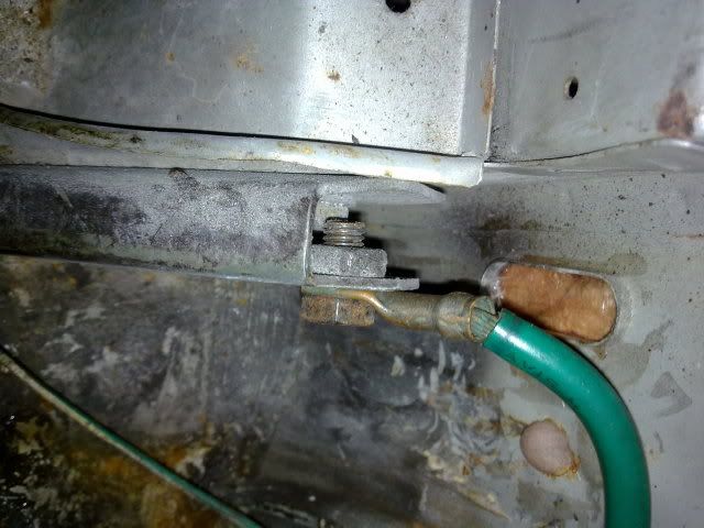 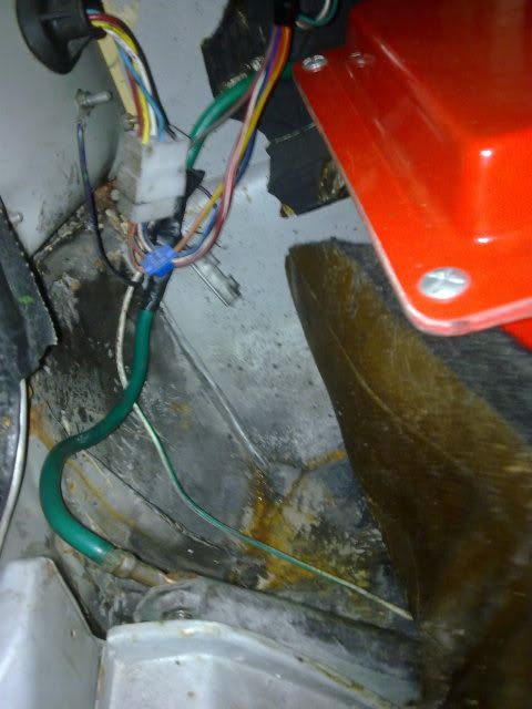 Cheers for that Geoff, i'll look them up when I get to that stage. I am aware of a few people having trouble with silicone hoses as you describe Eric, mainly them losing shape when under load, so may well use the motorcycle tube, if not have them solidly mounted to the manifold in some way. Valid point about the oil cooler, new is always best, i'll probably get new goodridge fittings/hoses, have it all set-up and in place with the vx items and measure up what I then need in new. I'll probably mount the oil cooler in front of the radiator, if I cant mount it by the side suitably. I probably won't make the NEC this year, but i'm sure i'll be at some event in the spring of next year to discuss con rods with you, I certainly won't need any til next year anyway! Monster of an engine would certainly be fitting for the purpose, what actual output from the proposed plans I get, I have no idea. Reliability and more bhp than standard would be a start  |
|
|
|
|
 Logged
|
|
|
|
|
Jimmie
Guest
|
 |
« Reply #105 on: November 23, 2010, 12:49:36 PM » |
|
Before registering for my question, I followed your project for quite a while, looking forward to seeing those throttle bodies in action  Two more questions. I noticed your rear strut brace. Did you make these or buy them off the shelf? A local tuner shop has some very nice looking adjustable strut braces with the main shaft being a thick piece of polished aluminun on sale for 50% off at US$25.00 each.
I'm also interested in the answer to this question, I was thinking about designing my own strut brace for front and rear for my sometimes trackdayed Beta Coupe, but while searching the BetaBoyz forum I found out you already have a strut brace at the rear. If you designed them yourself could you perhaps share the strut dimensions/spacing, would help me out a lot  |
|
|
|
|
 Logged
|
|
|
|
lanciamad
http://www.flickr.com/photos/lanciamad
Hero Member
    
 Offline Offline
 England
Posts: 699
Marcus Robinson
|
 |
« Reply #106 on: December 08, 2010, 04:30:22 PM » |
|
Hi, Yeh the rear strut brace is a home-made jobby. My initial idea was to have it computer designed (which i did) and send it through to the mill we had at college, which would have made perfect base plates by the hundred if I wanted, but the software required between computer and machine they hadn't purchased or got working so I ended up making one by hand which meant the finish wasn't great and i'm also a much better welder now!  The connecting shaft is hollow with a threaded sleeve welded either end which allows the fitment of rose joints either end for the perfect fit and easy fitting. I won't be making another or improving the current one as i'll be welding a solid bit of bar between the two struts as part of the roll cage, if that ever gets done. Base plate = i/d = 95mm o/d= 175mm with a pcd of 135mm (roughly); the connecting shaft is roughly 780mm but this is adjusted to fit depending on the bracket, hence the rose joints to be able to adjust the length. Bit more on the working progress manifold, I finished removing all the material I had to for the hoses... 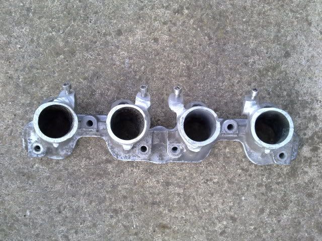 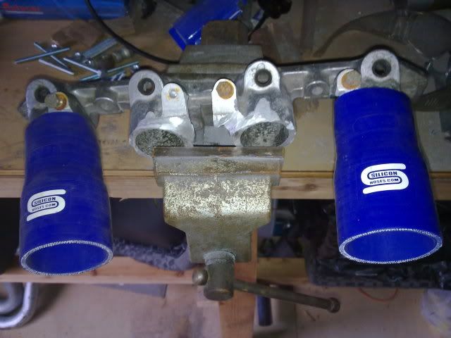 Quick mock up of what it'll look like... 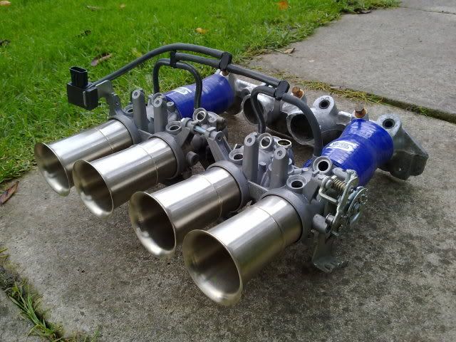 Some re-conditioned injectors with brand new rubbers fitted... 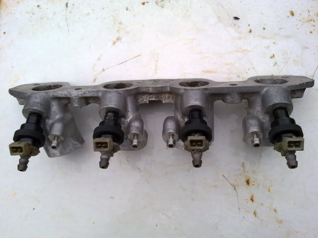 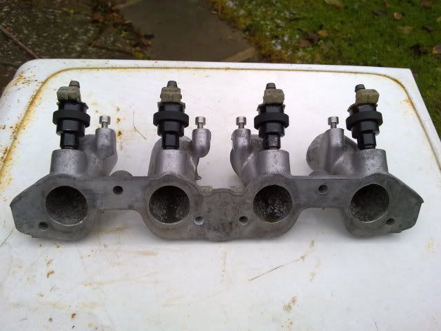 Latet mock up... 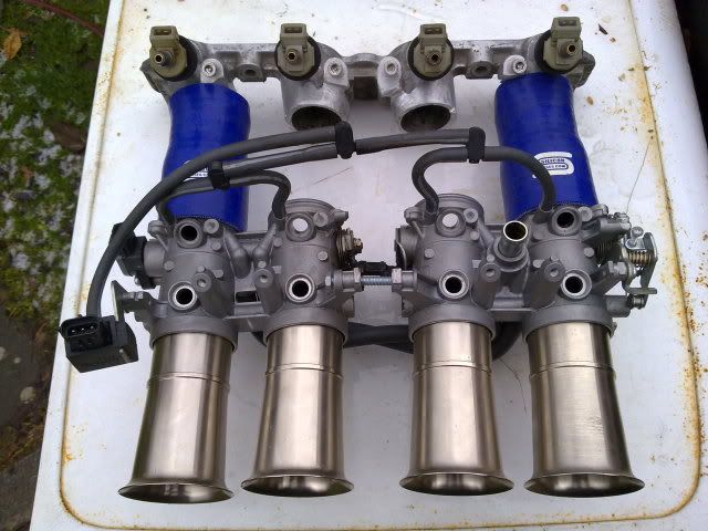 Things I can think of, that still need doing to the manifold and bodies are: Trumpets welded to bodies Bike injector holes blocked off Solidly space the bodies straight Fit hoses and clips Source/find the retaining plates for holding injectors in place Buy and fit fuel hose for injectors to rail Clean manifold Drill and have take off welded on for brake servo hose Port and polish manifold to intake gasket size Shout if ive missed something; now ive got a list to work to I better get on with it! |
|
|
|
|
 Logged
|
|
|
|
|
thecolonel
Guest
|
 |
« Reply #107 on: December 08, 2010, 09:27:30 PM » |
|
I may have missed something but how are you connecting to the air flow meter
or is that now obsolete ??
Geofff
|
|
|
|
|
 Logged
|
|
|
|
|
WestonE
|
 |
« Reply #108 on: December 09, 2010, 04:25:35 PM » |
|
Marcus
I assume you are using the bike body Throttle Postion Sensor in place of the airflow meter or a map sensor to measure load? Have you got the Pin outs for the TPS? Do you know what the flow rate is of those injectors and have you done the calculations to check they match your power expectations? You can buy injector pocket plugs from Jenvey if that helps. You need Nitrile hoses those silicon ones will not stand up to the petrol first going all soggy before collapsing under vacuum.
Keep going I look forward to hearing the beast in action.
Eric
|
|
|
|
|
 Logged
|
|
|
|
|
|
|
andybeta
|
 |
« Reply #110 on: December 12, 2010, 12:01:22 AM » |
|
Marcus,
Oil resistant reinforced silicon (with wire) tubing is available to stop it collapsing due to vacuum or being affected by oil, but it is pricey and has a substantially thicker wall than the silicon tubing you look to have acquired. Although not sure about petrol. Have you thought about using aluminium pipes in effect fabricating a manifold between TBs and the manifiold?
|
|
|
|
« Last Edit: December 12, 2010, 12:03:59 AM by andybeta »
|
 Logged
|
|
|
|
lanciamad
http://www.flickr.com/photos/lanciamad
Hero Member
    
 Offline Offline
 England
Posts: 699
Marcus Robinson
|
 |
« Reply #111 on: May 02, 2011, 12:56:37 AM » |
|
Apologies for the late reply. Project throttle bodies and project HPE have been on the back burner for a good few months since working on my HF Turbo which is almost complete now. After the lack of Beta's (no HPE) at Brooklands and the recent talk between friends about building a purpose built car for the track it has given me a bit of a kick up the ass regarding my HPE which has been sat on the drive too long now. The throttle bodies setup is still something I want to complete, as it has potential to improve performance for a very limited budget if my plans are successful. I will just have to have a good sort out in the shed and find everything I have and see if i've got everything I need to get it all setup; then get to work on the bodies and manifold and then go visit my friendly rolling road to get it all fitted and setup. Chances are I will invest in some hose as the colonel suggests as I only need to connect and not strengthen the setup as the manifold attaches as originally and the fuel rail will also fit as before, so the hoses/clips should be good enough to support the throttle bodies. First off, I found I DIDN'T have any holes in my floor as the water had collected pretty well from either a leak through the side window seal, sunroof or bulkhead, yet to be found. I'll have to get the hose pipe running from different angles and find where it's coming in... 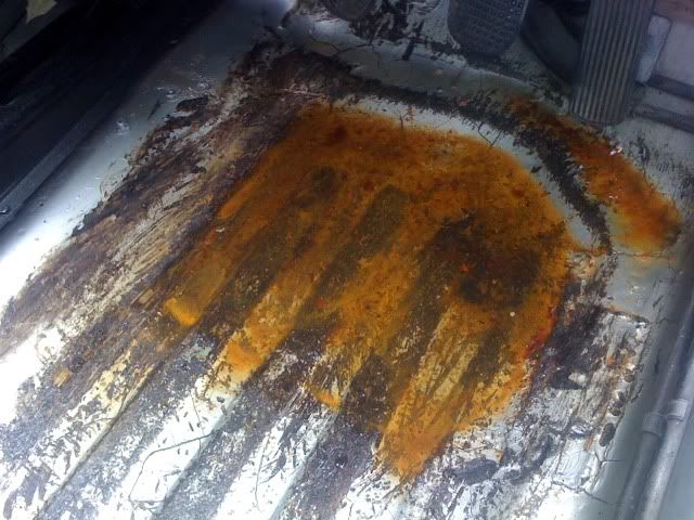 Next, the bonnet brackets have corroded and become so stiff when opening the bonnet the hinge was actually bending the metal around it and causing a crack in the metal... 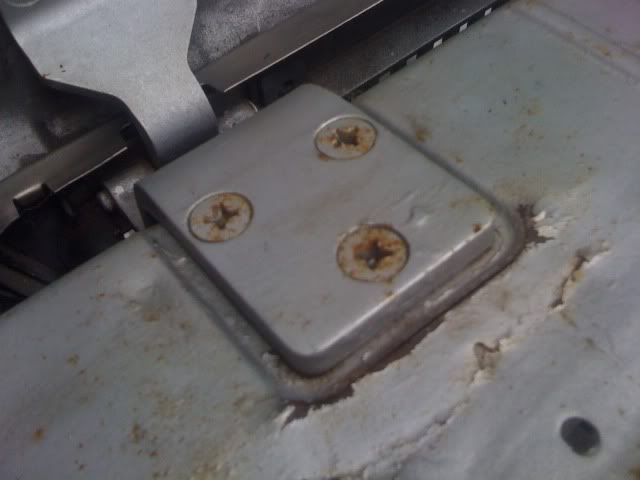 I've welded up the crack best I can, not ideal welding such thin/rusty metal but got there in the end. Now in primer ready to be sprayed met silver some time, hopefully some grease and WD40 will penetrate the joints and ease them off, if they don't i'll have to have the bonnet off and clean and grease the pins... 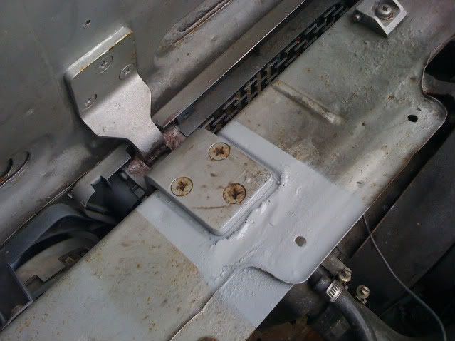 Onto some more modifications planned, not many Beta's have a roll cage in them never mind a HPE but thats the plan! I've had the B pillar hoop made about 3 years ago now and it just occupied the garage, but I pulled it out today and got to work, first sanding it down getting rid of some outer surface rust, cutting the legs down so it should now fit and spraying it in primer... 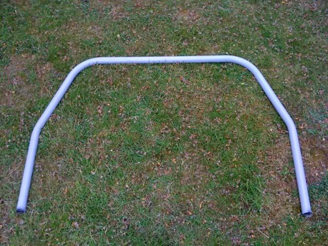 Once dried, i've given it a coat of smooth black. I know there will be some cleaning up needed to weld some bars to it, and obviously at the base where it will be welded to the chassis but the majority of the awkward areas to paint when welded in the car should be covered. I'll probably go for some brush on smooth black hammerite once the cage is completed... 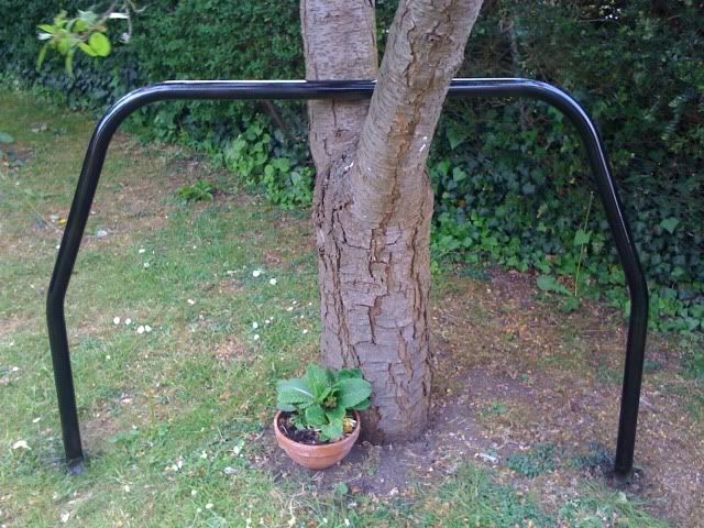 Current plan is to put it through it's MOT this month and get it back on the road for June. Once on the road then get the cage fully welded in and arrange for the outside to be rubbed down and re-sprayed as the paint has reacted with moisture over the months and come up with loads of pimples gradually getting worse across the whole car; he's happy to do it free of charge, but there is some tiny rust issues i'm happy to pay for and also the changing of the front wings for lighter options i'll expect to be paying for. I've got some plates, foot plates and gussets coming for the cage so will probably get them in place and then arrange for the A pillar to B pillar tubes to be made, with the rest just being straight pieces connecting the B pillar to rear turrets. |
|
|
|
|
 Logged
|
|
|
|
Grundo
Jr. Member
 
 Offline Offline
Posts: 43
|
 |
« Reply #112 on: May 02, 2011, 09:39:13 PM » |
|
I'm not sure if this comment is relevant but I know in this part of the world (NZ and AUS) when you get a roll cage approved by the motorsport governing body you need to have the cage either inspected or photos taken prior to painting after it has been installed. This is particularly around the welds on the plates to the body and the bends of the cage. I'm not sure if you have taken photos of the main hoop already or whether it has to be in the car etc but I would assume the UK is as strict as others seeing as it all adheres to the FIA regulations.
Hopefully this is a wasted comment and you are on top of it!
|
|
|
|
|
 Logged
|
|
|
|
lanciamad
http://www.flickr.com/photos/lanciamad
Hero Member
    
 Offline Offline
 England
Posts: 699
Marcus Robinson
|
 |
« Reply #113 on: May 02, 2011, 10:34:11 PM » |
|
No your quite right in saying so, to be FIA approved it needs to be fitted and welded in by an FIA approved welder. I am however not to fussed about this as the car will never be raced in a competitive nature, it is being built to somehow still be road legal as well as mainly being a well sorted track car. I plan to keep the car and will never be able to afford to go racing and if I could it certainly wouldn't be in the HPE! The prices i've had quoted for a cage to be made are can only be described as horrendous, hence the route i'm going. If it comes down to it, i'm pretty sure you can organise test pieces to be sent out to you, weld them in place and send back for assessment, to class you as an approved welder, and would class it FIA approved if need be.
|
|
|
|
|
 Logged
|
|
|
|
lanciamad
http://www.flickr.com/photos/lanciamad
Hero Member
    
 Offline Offline
 England
Posts: 699
Marcus Robinson
|
 |
« Reply #114 on: May 18, 2011, 09:07:59 PM » |
|
Finally got around to welding up my front struts with modifications so it's now a fixed -2 degrees negative camber on the front, with future plans of adjustable top mounts for increased camber changes, but this will only be when I get the car going any faster than standard trim with suitable braking upgrades to match... 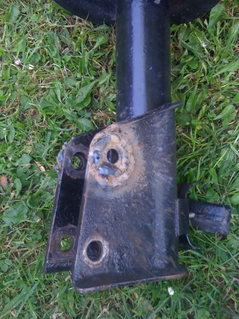 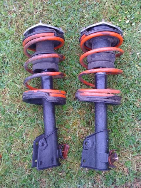 Spent the best part of a day making up plates for the roll cage to sit on, plenty of welding, grinding and filing produced this lot... 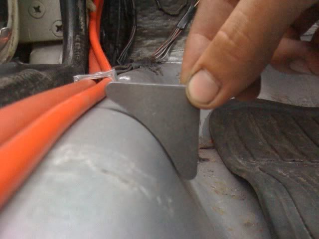 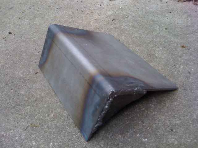 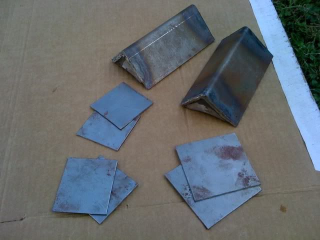 I've decided that I don't want to cut away at the dash, so am going to fit the A pillar mounting just in front of the dash which should also just clear the inside door handles... 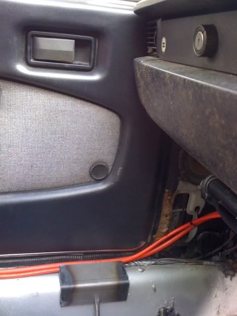 Got my A pillar to B pillar tubes bent, should fit perfectly once cut down, the cardboard never lies... 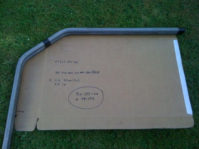 and with the car booked in tomorrow for the MOT, I had a few little jobs to sort out, one being replacement front wipers; so I opted for some modern style aero wiper blades... 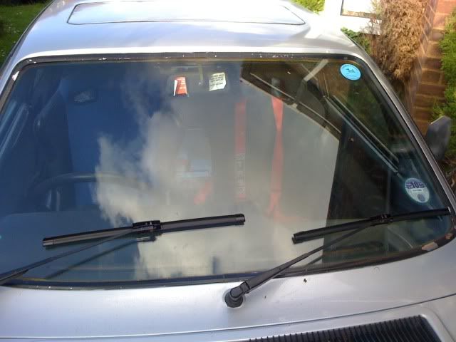 I'm pretty confident the floor pan to sill join is going to need attention and possibly a bit on the rear turret, but other than that pretty happy with the rest, see how she gets on I suppose  Gives me a couple of weeks to get it sorted anyway. |
|
|
|
|
 Logged
|
|
|
|
lanciamad
http://www.flickr.com/photos/lanciamad
Hero Member
    
 Offline Offline
 England
Posts: 699
Marcus Robinson
|
 |
« Reply #115 on: May 19, 2011, 09:43:58 PM » |
|
Well that made my day, turns out I didn't need those couple of weeks, went straight through with just a comment about getting the last ancient road tyre i'm trying to wear down, replaced; happy motoring  As soon as June comes around, should be back on the road for more fun, see if I can improve on the 995 miles I covered in it over the last year  and see about this roll cage and bodywork re-spray mk2. |
|
|
|
|
 Logged
|
|
|
|
|
cheeky monkey
|
 |
« Reply #116 on: May 19, 2011, 11:42:46 PM » |
|
Good stuff!. keep your fingers x'd please.. my MOT is 2pm tomorrow  |
|
|
|
|
 Logged
|
Graham
1979 beta coupe 1300
|
|
|
|
|
|
MattNoVAT
|
 |
« Reply #118 on: May 30, 2011, 08:49:12 AM » |
|
You have been busy Marcus! - good to see the progression.
I have a question about your roll cage design, why did you not extend the front section to the point where it would follow the roofline and then butt up against the A pillar? I would have thought that it would have provided a bit more strength in the event of any impact, or have you kept it a few inches away from the A pillar so it acts as a kind of crumple zone and the A pillar absorbs the initial impact and then the cage does its bit after the impact forces have been reduced?
It's not a criticism, just trying to work out if design has improved over time. On my old grass tracking VX Coupe I recall the Safety Devices cage I recall that the vertical sections were aligned and tight against the A & B pillars but that was 12 - 13 years ago!
The support platforms you have fabricated are almost identical like those provided with the Safety Devices cage I had.
|
|
|
|
|
 Logged
|
1981 2000 Coupe S2/FL
1976 1600 Coupe S1
2007 Ypsilon 1.3 Bi-Colori
|
|
|
lanciamad
http://www.flickr.com/photos/lanciamad
Hero Member
    
 Offline Offline
 England
Posts: 699
Marcus Robinson
|
 |
« Reply #119 on: May 30, 2011, 11:46:33 AM » |
|
You've been damn busy yourself from what i've seen  Your have yours on the road before I finish this cage! I would have liked to extend it forward onto the A pillars, as I expect some of the available cages would do? But as i'm trying to do it to a budget (as usual) I was restricted to the sharpness the tubes could be bent to by my local motorsport shop (you can probably notice in the pic the angles are not of the same shape as the A pillar) and also the length of tubes. I'd have to pay an extra £20 per tube for another metre of which i'd only use 10cm's roughly, so I can live with it. TBH it's all work in progress, i've got the design in my head but constantly changes when i'm fitting it. From looking at it sat in the seat, I can only see the A pillar absorbing the impact (heaven forbid) and hitting the bar, so either way should do it's job effectively, hopefully never to be tested! As you can see in the last pic, the A pillar tube mounts towards the rear of the platform. I was actually expecting it to be fitted in the middle, but once i'd cut it down and changed the angle it ended up being towards the back; so design change again, once the cage is effectively done, i'm going to triangulate at the platform with some of the many off-cuts of tube which should support the tube a lot more and double the area of impact in the case of rolling; I mean strengthen the chassis up some more  I'm glad I fitted pretty decent spreader plates, especially for the B pillar mounts, when welding them in and building up some pretty decent heat I managed to put a small hole through (which got welded up), and considering thats one of the cleanest bits of metal, it concerned be a bit when I came across a chap abroad that had welded straight to it; it wouldn't surprise me if the cage went straight through it on impact. This morning I cut the tubes from B pillar to rear turrets, so am ready to fit most the cage now, just need to do a little grinding and weld everything in; damn weather  Only thing I haven't decided on is the rear diagonal tube, it's going to be mounted from one of the top corners of the B pillar but haven't decided where to mount the other end, can you remember where it did on yours Matt? Anyone got some pics to give some inspiration? |
|
|
|
|
 Logged
|
|
|
|
|


